Component structure
Measurement codes and translation rules are created and attached to specific failure modes so the measurements and any associated alert can be assigned to a possible component failure. Failure modes are assigned to components by setting up a component structure.
The component structure defines the failure modes for a particular component by model of equipment. This structure is later assigned to particular items of plant.
The component structure hierarchy comprises four levels:
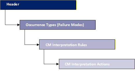
The number of levels completed in the hierarchy and the detail entered depends on your objectives.
- For condition based maintenance all four levels must be completed.
- For reliability centred maintenance or component contingency, only the first two levels need to be completed.
To create a component structure, navigate to Knowledge Database > Condition Based Maintenance > Component Structures. The Component Structure Manager dialog box opens. Click Add  .
.
Component structure dialog box overview
Icons
| Icon | Description |
|---|---|

|
Refresh. |

|
Save. |

|
Close the dialog box. |
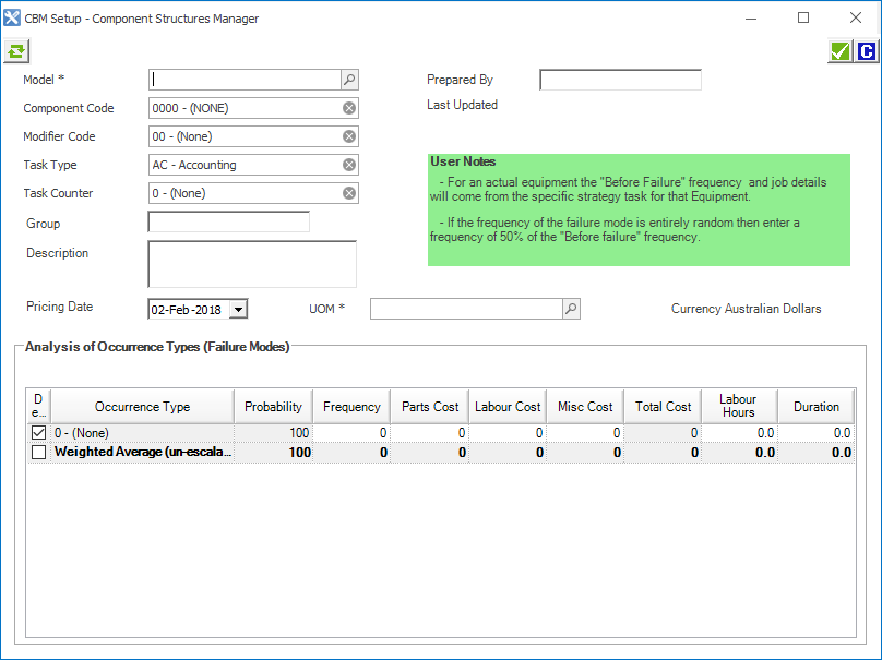
Component structure header (top section)
Contains header information about the Component Structure, particularly what model and component it relates to.
Fields and columns
| Column | Description | Example |
|---|---|---|
| Model | The type of asset. |
793C, WAR001. |
| Component Code | Indicates which component the measurement was taken from. | 4000 for Engine. |
| Modifier Code | A code that provides additional identification to the component code, typically the component's location on the asset. |
RF - Right Front. TP - Top. |
| Task Type | A code and description combination identifying what is to happen at an occurrence of a strategy task. |
AC - Accounting. |
| Task Counter | Identifies the sequence in which a strategy task is performed. |
1st - First Overhaul. 365 - 365 Day Service. |
| Group | Lets you set up multiple component structures for the same component and model, which may be required for different applications. | |
| Pricing Date | This field is for information purposes only, it indicates the pricing date for the costs set up in the occurrence types. It has no impact on financial forecasts. | |
| UOM (Unit of Measure) | A defined unit of measure. |
ENG - Hrs Engine Hours Fuel - Lt Days |
Analysis of occurrence types (failure modes)
Within a component structure there can be many occurrence types. These are displayed in the grid.
| Column | Description | Example |
|---|---|---|
| Default | The generic ‘before-failure’ scenario (that is, if there is no failure what is the expected life of a component). |
Select the check box. |
| Occurrence Type | The failure mode. Failure modes should reflect the component's failed state and why it failed. | Ceased – piston failure |
| Probability | The probability of all of the occurrence types. Must add up to 100%. | 100%. |
| Frequency | The UOM between projected occurrences. | 15,000 (engine hours between each engine replacement). |
| Parts Cost | The cost of Parts. | |
| Labour Cost | The cost of Labour. | |
| Misc Cost | Any Miscellaneous Costs. | |
| Total Cost | The total cost of the failure. | |
| Labour Hours | The number of labour hours. | |
| Duration | The duration of the failure. |