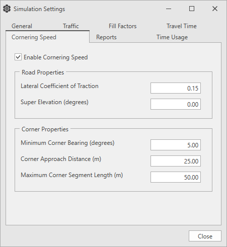
Set the cornering speed by clicking the main menu, then select Simulation Settings > Cornering Speed tab.
When a vehicle travels around a corner (of a given radius), a force (centripetal force) is required to make the vehicle follow the corner. The maximum velocity of a vehicle can be calculated by calculating the force available to the vehicle through traction (friction between the vehicle and the road) and the super elevation (banking of the road).
The Road Properties determine what the speed limit should be for the equivalent radius.
The Corner Properties determine which road segments to include in a corner, and from that, the equivalent radius of the corner.
| Field |
Description |
|---|---|
| Enable Cornering Speed | Select this check box to enable cornering speed. |
| Lateral Coefficient of Traction | Determines the maximum tractive (friction) force available when the truck is turning the corner. |
| Super Elevation (degrees) | Specifies the angle at which the road is banked. |
| Minimum Corner Bearing (degrees) |
If the change in bearing between two segments is less than the minimum corner bearing, the segments are not considered as part of a corner. |
| Corner Approach Distance (m) | The segments leading into and out of a corner contribute to the total corner length during the cornering calculations. The Corner Approach Distance determines the maximum length of the segment to be considered as part of that corner. |
| Maximum Corner Segment Length (m) | Road segments that are longer than the Maximum Corner Segment Length are not included in a corner. |
When cornering speed is enabled, speed limits are automatically applied to haul segments that have corners. The cornering speed algorithm works in two phases; first, an equivalent radius is estimated for a corner, second, the equivalent radius is used to calculate the speed limit for the corner.
The road network in the 3D model consists of many straight road segments of various lengths and grades. Road segments that are grouped together to make a corner are used to calculate the equivalent radius by adding the total length of the road segments in the corner as well as the corner approaches (In and Out) and the total change in bearing of the road segments in the corner.
Equivalent Radius = Length/Change in Bearing (Radians)
Once the equivalent radius of the corner is calculated, it is used to determine the maximum speed that the vehicle can travel around the corner. When a vehicle travels around a corner, a force (centripetal force) is required to make the vehicle follow the corner. The maximum velocity of a vehicle can be calculated by calculating the force available to the vehicle through traction (friction between the vehicle and the road) and the super elevation (banking of the road).
Limiting velocity by Lateral Traction Coefficient
Max Velocity (m/s) = (Radius x 9.81 x Lateral Coefficient of Traction)
Limiting velocity by Super Elevation
Max Velocity (m/s) = (Radius x 9.81 x Tan(Super elevation))
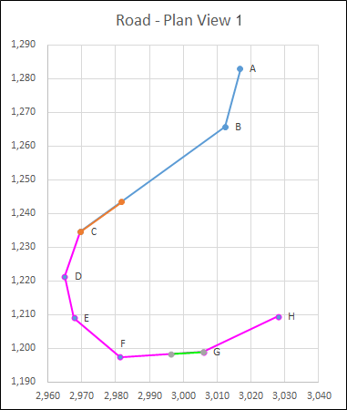
Consider the two haul routes below, Road - Plan View 1 and Road - Plan View 2.
In Road - Plan View 1, the Maximum Corner Length for the haul route is set at 50m, so the segments combine into one corner, and in Road - Plan View 2, the Maximum Corner Length for the haul route is set at 20m, decreasing the radius of the corner. The Corner Approach Distance of 15m is used when approaching a corner.
| Road Properties | |
| Lateral Coefficient of Traction | 0 |
| Super Elevation | 5 |
| Corner Properties | |
|
Minimum Corner Bearing (Degrees) |
10 |
| Corner Approach Distance (m) | 15 |
| Maximum Corner Length (m) | 50 |
|
Segment |
Length (m) | Bearing (Degrees) |
Change in Bearing (Degrees) | Minimum Change in Bearing Satisfied | Maximum Corner Segment Length | Corner | Equivalent Radius | Corner Speed |
|---|---|---|---|---|---|---|---|---|
| AB | 18 | 194 | 0 | Fail | Pass | 1 | ||
| BC | 53 | 234 | 40 | Pass | Fail | 1 | 42.03 | 21.62 |
| CD | 14 | 200 | -34 | Pass | Pass | 2 | 33.21 | 19.22 |
| DE | 13 | 167 | -33 | Pass | Pass | 2 | 33.21 | 19.22 |
| EF | 18 | 130 | -37 | Pass | Pass | 2 | 33.21 | 19.22 |
| FG | 25 | 87 | -43 | Pass | Pass | 2 | 33.21 | 19.22 |
| GH | 24 | 64 | -23 | Pass | Pass | 2 | 33.21 | 19.22 |
| HI | 40 | 60 | -4 | Fail | Fail | 0 | 0 | 0 |
Length = 15(AB Approach) + 15 (BC Approach) = 30m
Change in Bearing = 40 (AB:BC) Degrees
Equivalent Radius (m) = 30/Radians(40Degrees) = 42
Max Velocity (km/hr) = = 3.6 * SQRT(42 * 9.81 * (SIN(5) + (0 * COS(5))) / (COS(5) - (0 * SIN(5))))
Length = 15 (BC Approach) + 14 (CD) + 13 (DE) + 18 (EF) + 25 (FG) + 15 (GH Approach) = 99m
Change in Bearing = 34 (BC:CD) + 33 (CD:DE) + 37 (DE:EF) + 43 (EF:FG) + 23 (FG:GH) = 170 Degrees
Equivalent Radius (m) = 99/Radians(170Degrees) = 33
Max Velocity (km/hr) = 3.6 * SQRT(33 * 9.81 * (SIN(5) + (0 * COS(5))) / (COS(5) - (0 * SIN(5)))) = 19.2
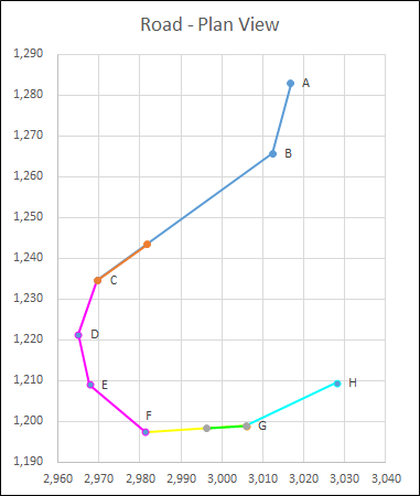
If you change the Maximum Corner Length to 20m, the results are shown in the graph and tables below.
| Road Properties | |
| Lateral Coefficient of Traction | 0 |
| Super Elevation | 5 |
| Corner Properties | |
|
Minimum Corner Bearing (Degrees) |
10 |
| Corner Approach Distance (m) | 15 |
| Maximum Corner Length (m) | 20 |
| Segment | Length (m) | Bearing (Degrees) |
Change in Bearing (Degrees) | Minimum Change in Bearing Satisfied | Maximum Corner Segment Length | Corner | Equivalent Radius | Corner Speed |
|---|---|---|---|---|---|---|---|---|
| AB | 18 | 194 | 0 | Fail | Pass | 1 | ||
| BC | 53 | 234 | 40 | Pass | Fail | 1 | 21.62 | 42.03 |
| CD | 14 | 200 | -34 | Pass | Pass | 2 | 17.87 | 38.7 |
| DE | 13 | 167 | -33 | Pass | Pass | 2 | 17.87 | 28.7 |
| EF | 18 | 130 | -37 | Pass | Pass | 2 | 17.87 | 28.7 |
| FG | 25 | 87 | -43 | Pass | Pass | 3 | 17.87 | 28.7 |
| GH | 24 | 64 | -23 | Pass | Pass | 4 | 29.24 | 76.87 |
| HI | 40 | 60 | -4 | Fail | Fail | 0 | 0 | 0 |
You can see the effect of changing corner speed, length and angle values using the cycle time tool. Please see Related topics below.
Related topics