Configure the key properties of materials on the Build and Run tab.
The properties that are configurable include:
These properties affect load time calculations. The properties that are considered during the load time calculation and their influence on the calculation are listed below.
Load and Haul Loading Times tab
Load and Carry Loading Times tab
| Type | Description |
|---|---|
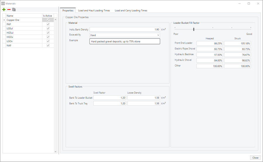
| In situ Bank Density |
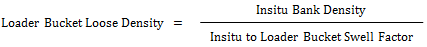
The in situ bank density of the material is the density of the material in the ground before it is disturbed. In situ Bank Density and Loose Density are expressed as t/m3 in Metric and lb/yd3 in US Units. |
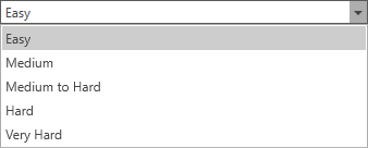
| Excavatability |
Whether the material is easy or hard to excavate. Options are:
|
| Type | Description |
|---|---|
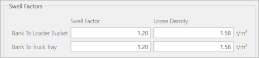
| Bank to Loader Bucket | Swell Factor, Loose Density – As the material is loaded from the ground, it swells, increasing in volume. The density of the material decreases due to the swelling. |
| Bank to Truck Tray | Swell Factor, Loose Density – As the material is dumped into the tray of the truck, it swells, increasing in volume. The density of the material decreases due to the swelling. |

The swell factor can be any number greater than zero, however, it would most commonly be between 1.0 and 1.5.
The Bank to Loader Bucket Loose Density also displays and is calculated using this formula:
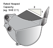
The loader bucket fill factor is a measure of how a particular material fits into a bucket, in comparison to the rated capacity of the bucket. The reason for the difference in these two values is that the rated capacity may be measured using a struck or various heaped ratings, while the material rills at a particular angle (the angle of repose) in the bucket. The angle of repose of the material may be greater or less than the angle of repose used to measure the rated heaped volume. The following diagram illustrates this concept:
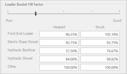
The loader bucket fill factors are stored with the material data because they are dependent on the material characteristics. The fill factors are also dependent on the geometry of the loader bucket. Different values are stored for the different loader classes.
The loader bucket fill factor is determined by the following ratio:
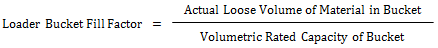
The volumetric rated capacity of the loader bucket is expressed on a struck or a heaped basis. Similarly, the loader bucket fill factor must be expressed on a struck or a heaped basis. The fill factor is usually between 0.5 and 1.5.
In the material configuration, the values for the loader bucket fill factor display for both a struck and a heaped basis. They also display for the different loader classes:
When a loader configuration is selected, FPSim determines which loader class it belongs to (from the equipment library), and then matches this template with the relevant fill factor.
Select the fill factor from the sliding scale or type it into the fields.
If the fill factor value entered is outside the limits, then the value is restricted to the minimum or maximum fill factor, as appropriate.
These definitions are in the Excavatability list.
| Fill Factor | Definition |
|---|---|
|
Very Hard |
Poor + 0% * (Good – Poor) |
| Hard | Poor + 25% * (Good – Poor) |
| Medium to Hard |
|
| Medium |
|
| Easy |
|
The global Loader Bucket Fill Factors for each of the different loader classes are configured on the Simulation Settings dialog box.
On this tab, you can specify loading times, and pass matching between loading units and haulage units. It requires a truck and loader combination to be selected.
Truck and loader types must be added prior to this step.
The number of passes and mean time to load a truck is shown in this panel and will be dependent on the truck and loader combination selected.
Truck and loader types must be added prior to this step.
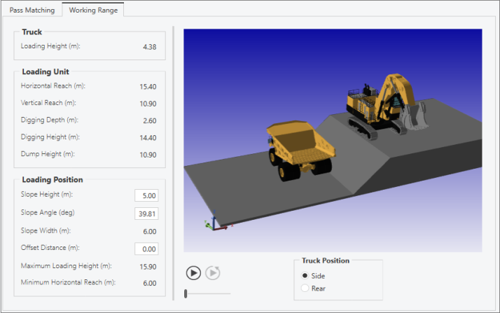
On this tab you are able to visualise the truck and loader working together. You can adjust the slope height and angle to reflect the site configuration. Play the animation to assist with visualisation.
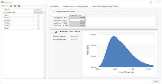
The Load and Carry Loading Times tab lists loading times for the load and carry unit.
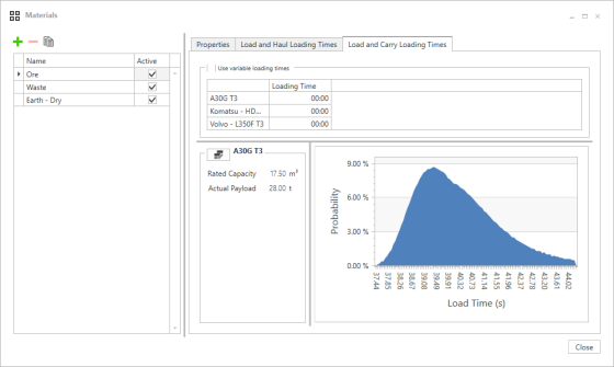
Distribution data displays after selecting a load and carry type and selecting Use variable loading times.