The haul route is typically split up into segments, which account for changed topographical and operational conditions along the haul route. Each travel segment in the haul route requires the following information:
The number of haul segments into which a haul route is divided depends on the variability of the haul route and the accuracy required from your results. Use the following suggestions as a guide:
The segment distance is the distance that the truck travels within the segment. The sum of the segment distances should be the total length of the haul network.
When a segment is on a grade, the distance should be the actual distance over which the truck travels, that is, the distance along the grade.
The grade of the haul segment is expressed as a percentage. The percentage represents the vertical rise divided by the horizontal distance. For example, a grade of 10% represents a rise of 10 metres over a horizontal distance of 100 metres.
An ascent has a positive grade, while a descent has a negative grade. Typical ramp grades are in the range of 6% to 12% or -6% to -12%).
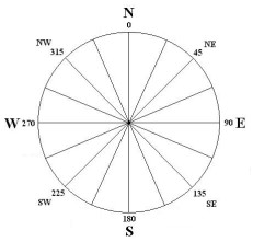
The bearing defines the direction in which the road segment is heading. A bearing of 0° will be due north.
Use the change in bearing to change the bearing from one segment to the next segment. The change in bearing is linked to the bearing in the segment before the segment that it is being applied to.
| A - Segment | B - Bearing (Degrees) | C - Change in Bearing (Degrees) |
|---|---|---|
| 1 | 70 | 0 |
| 2 | 80 (B2=B1+C2) | 10 |
| 3 | 60 (B3=B2+C3) | -20 |
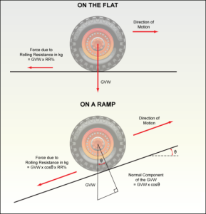
Rolling resistance is the result of the frictional force that occurs between the truck tyres and the ground surface. This frictional force is directed at a tangent to the truck tyres, that is, parallel to the ground surface, and acts in the opposite direction to the motion of the truck. The greater the gross vehicle weight of the truck, the greater the rolling resistance.
The rolling resistance is expressed as a percentage of the component of the gross vehicle weight that is normal (perpendicular) to the ground surface. The normal component of the gross vehicle weight changes within the haul profile as grade and truck payload change. The percentage rolling resistance also changes as the surface changes from smooth to rocky and rough. Therefore, the force due to the rolling resistance changes along the haul profile. The following diagram illustrates the way in which rolling resistance changes with ramp grade.
The following table provides a guide to rolling resistance values for a variety of road conditions.
| Haul Road Location | Rolling Resistance |
|---|---|
| Around Loader | 3.0 |
| Bench Floor | 2.5 |
| Pit Ramp | 2.5 |
| Main Haul Road | 2.0 |
| Dump | 2.5 |
It is not always the rolling resistance, gradient or sharpness of curves that determines the speed of the machine. Roughness of the surfaces of the loading area, haul route and dump area also affect the speed of the machine.
The roughness does not have to be particularly severe to subject both the operator and machine to high stresses due to shaking and vibration.
The operator instinctively adapts the speed to a level that is easy on both the machine and themselves. This speed varies with the roughness of the surface and comfort and safety of different machines.
Depending on the size and nature of the obstacles, the running surface can be classified in the following ground structure class:
| Group | Maximum distance between obstacles, 5m (16ft) | |||||
|---|---|---|---|---|---|---|
| Ground Structure Class | ||||||
| 0.0 | 0.2 | 0.4 | 0.6 | 0.8 | 1.0 | |
| Hard ground with solid obstacles (Gravel road) cm (in). |
0 - 2 | 2 - 3 | 3 - 4 | 4 - 6 | 6 - 10 | 10 - 30 |
| 0 - 0.8 | 0.8 - 1.2 | 1.2 - 1.6 | 1.6 - 2.4 | 2.4 - 4.0 | 4 - 12 | |
|
Soft ground with soft obstacles (Wet clay) cm (in).
|
0 - 3 | 3 - 4 | 4 - 6 | 6 - 10 | 10 - 30 | 30 - 40 |
| 0 - 1.2 | 1.2 - 1.6 | 1.6 - 2.4 | 2.4 - 4.0 | 4 - 12 | 12 - 16 | |
For each truck, a ground structure table can be set up that defines the maximum speed (full and empty) to apply when the vehicle is travelling across a road. The ground structure field on the road property determines the maximum speed from the table to be used. The ground structure table is in the equipment library. A ground structure of 0 (default) will not limit the speed.
The delay time, in seconds, that the truck will wait in the middle of the segment before continuing the trip.
If there is a Trolley is selected for a given segment, the trucks that have trolley information (trolley and trolley fuel or electricity curves) use it in the calculations, instead of the normal propulsion and fuel curves.
The maximum final speed a truck can reach in a segment, due to an approaching corner.
The maximum speed a truck can travel through a segment, due to cornering properties.
The calculated radius based on the cornering properties. (Refer to Cornering Speed).
When a haul route is created, it is assumed that the start location (source) is at the start of the haul route before the first segment. The end location (destination) is always at the end of the haul route after the last segment. You can click the reverse button can be used to reverse the order of the segments in the haul route.