Create markup
Markups can be added to the 3D Scene to highlight features or add work notes. Markup types include notes, arrows and polylines.
The markup control is a floating icon in the lower left of the 3D Scene.
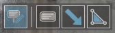
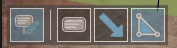
Click the Markup icon  to show the individual markup icons.
Selection mode
Click on an existing markup to have their properties panel appear, and edit properties that change the markup appearance.
Edit mode
Click the Markup icon to show individual markup icons, the shape and properties of the selected markup can now be changed.
Selected markups can be removed with the Delete key.
In this mode you can also add a Note markup to any selected item (Activity areas, Resources and so on) in the Scene by selecting the item > right-click > click the Note icon in radial menu.
Draw mode
Click one of the individual markup icons to enter draw mode, see steps below for markup creation.
Markup creation
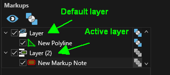
Markups are organised by default under a markup Layer as displayed in the Markups tab. To create a markup in a specific layer, first create the layer then make it active. See Markups tab.
| Markup Type | Controls |
|---|---|
| Notes |
Create Note markup
Edit markup properties
Edit markup location
Markup context menu Use the Markup context menu to add arrows to, or remove arrows from, the textbox.
|
| Arrows |
Edit markup properties
Edit markup location
Markup context menu
|
| Polylines |
Edit markup properties
Edit markup location
Markup context menu
|

 and Edit mode
  .
. /arrow to add an arrow to the textbox
 - removes the newly created arrow.
 , or set Is Closed in the items Properties panel.
  .
. .
.Markup Properties
| Notes | Description |
|---|---|
| General\Text | The content of the note markup. |
| General\Shape Style | The shape and colour of the note outline. Click the ellipsis button to set the outline transparency. |
| General\Background Colour | The colour of the markup background. Click the ellipsis button to see the markup transparency. |
| General\Overlay | Enable to have the markup draw as an overlay (draped over the topographic surface). |
| Font\Font | The text font type and size settings. |
| Font\Style | The text style settings. Click the ellipsis button to set the text transparency. |
| Font\Alignment | The position of the textbox alignment node. |
| Lines\Border | Switch to enable the textbox border and set the border width. |
| Lines\Arrows | Switch to toggle arrows and set the arrow line width. |
| Lines\Arrowhead | Switch to enable arrow head and dropdown to set the arrowhead type. |
| Geometry\Position | The coordinate position of the alignment node. |
| Geometry\Angle | The angle (degrees) counter-clockwise of the textbox around the alignment node. |
| Arrows\X | X coordinate of the arrow heads. |
| Arrows\Y | Y coordinate of the arrow heads. |
| Arrows\Z | Z coordinate of the arrow heads. |
| Arrows Markup | Description |
|---|---|
| Arrow Shaft\Overlay | Enable to have the markup draw as an overlay (draped over the topographic surface). |
| Arrow Shaft\Colour | The colour of the arrow. Click the ellipsis button to set the markup transparency. |
| Arrow Shaft\Style | Set the line style and width. |
| Arrow Heads\On First Point | Switch to enable an arrow head at the arrow start. Once enabled, the style and width can be set. |
| Arrow Heads\On Last Point | Switch to enable an arrow head at the arrow end. Once enabled, the style and width can be set. |
| Geometry\RL | Locks the vertex Z value to the entered RL elevation. |
| Geometry\Absolute | The absolute coordinates of the vertex. |
| Geometry\Relative | The coordinates of the vertex relative to the previous vertex. |
| Geometry\Distance,Bearing,Elevation | The relative distance, bearing and elevation of the vertex from the previous vertex. |
| Geometry\Set Point, Add Point |
In Edit mode - Button to apply the position transformation defined in the Geometry fields to the selected vertex. The coordinates of the vertex in the point grid will update to new values. In Draw mode - Button to add a vertex at the position defined in the Geometry fields. A new row will be added to the vertex grid. |
| Geometry\X |
X coordinate of the selected/added vertex. |
| Geometry\Y | Y coordinate of the selected/added vertex. |
| Geometry\Z | Z coordinate of the selected/added vertex. |
| Polyline Markup | Description |
|---|---|
| Polyline\Overlay | Enable to have the markup draw as an overlay (draped over the topographic surface). |
| Polyline\Is Closed | The colour of the arrow. Click the ellipsis button to set the markup transparency, and the shape and colour of the note outline. Click the ellipsis button to set the outline transparency. Enables or disables any cutting planes in the scene. This is the legend to use for the blocks. |
| Polyline\Colour | The colour of the markup background. Set the line style and width. Click the ellipsis button to set the markup transparency. An expression that returns true or false based on properties of the blocks; blocks that return true will be visible. When Cutting Planes are enabled, clicking this icon will allow the cursor to create cutting planes when click-dragging in the scene. The icon changes to a grey background when it is active. |
| Polyline\Style | Switch to enable an arrow head at the arrow start. Once enabled the style and width can be set. Enable to have the markup draw as an overlay (draped over the topographic surface). The count of blocks that return true from the Expression. Toggle visibility of the cutting planes. Cutting planes appear as grey semi-transparent planes in the scene. Click-drag on the visible plane to move the cutting plane perpendicular to its orientation. |
| Fill/Colour |
Switch to enable an arrow head at the arrow end. Once enabled the style and width can be set. Removes all cutting planes from the scene. The text font type and size settings. Option to exclude blocks from outside pit limits. |
| Geometry\RL | Locks the vertex Z value to the entered RL elevation. |
| Geometry\Absolute | The absolute coordinates of the vertex. |
| Geometry\Relative | The coordinates of the vertex relative to the previous vertex. |
| Geometry\Distance/Bearing/Elevation | The relative distance, bearing and elevation of the vertex from the previous vertex. |
| Geometry\Set Point |
In Edit mode - Button to apply the position transformation defined in the Geometry fields to the selected vertex. The coordinates of the vertex in the point grid will update to new values. In Draw mode - Button to add a vertex at the position defined in the Geometry fields. A new row will be added to the vertex grid. |
| Geometry\X |
X coordinate of the selected/added vertex. |
| Geometry\Y | Y coordinate of the selected/added vertex. |
| Geometry\Z | Z coordinate of the selected/added vertex. |