Creating dependencies graphically |

|

|
|
Creating dependencies graphically |

|

|
Generic dependency rules that are applied to large areas of a mine are normally responsible for creating most of the dependency rules in XPAC projects. These types of rules are very flexible and each one can create many thousands of individual dependencies.
But at most mines there are areas that do not follow the general rules. Although script rule sets are commonly applied in these areas, it is often simpler to create the dependencies manually using absolute address rule sets.
The standard method for creating absolute address dependency rules is to drag predecessors from a database tree, after the successor has been selected. Although this is very efficient, it is sometimes more intuitive to select the records from a graphical image of the deposit. This is particularly true in mines where the deposit has been subdivided in an irregular manner or where the record names do not indicate their relative positions.
XPAC allows any spatial data plot to be used to create dependency rules, with all standard graphics tools such as colour coding and record annotation available. Furthermore, the tools allow both standard dependency rules and OR rule groups to be created.
These facilities make use of the docked windows associated with each plot. These windows are very useful, but can be difficult to master initially.
Before dependency rules can be created graphically, the plot that will be used to define the dependencies must be displayed. A new template can be created for this purpose or an existing template can be used. The graphics window should be maximised when creating dependency rules and the docking windows must also be well organised.
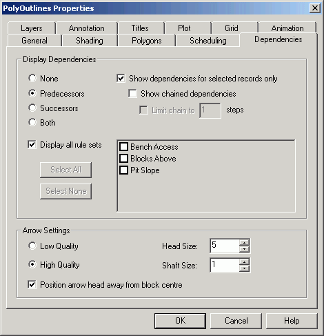
The Dependencies tab in each plot's Properties window is used to control how dependencies are displayed on the graphics image. We recommend the following settings be selected when the plot is being used to create dependencies.

| • | The Predecessors option should be chosen in the Display Dependencies frame, with the Display all rule sets check box ticked. |
| • | The Show dependencies for selected records only check box should be ticked but the Show chained dependencies check box should not be ticked. |
| • | High quality arrows should be selected with a Head Size and Shaft Size for the arrows set to fairly low values (5 and 1). These will have to be adjusted to suit the size of the blocks being displayed. |
| • | The Position arrow head away from block centre check box should be ticked. |
We also recommend that shading is not used in the image unless absolutely essential as it can obscure the dependency arrows that are drawn between the centroids of related records. If shading is being used, the extrusion depth should be set to zero and large, high quality arrows should be used.
Once the plot has been displayed, the Create/Edit Dependencies button should be clicked and the Dependency Rule View should be opened. This can either be docked to an edge of the screen or left to float over the image.
In most instances, all other docking windows should be closed. The Record Tree View is only required when switching between different parts of the deposit (switching between benches in an open pit, for example) after setting appropriate options in the Graphics > Record Tree View menu.
Most users will determine the window layout that best suits their requirements. A good starting point is with both the Dependency View and the Tree View docked on the right hand side of the screen, with the Tree View on the bottom. The window splitter should also be adjusted so the full width of the Dependency View is visible.
The Tree View is normally left hidden, but can be displayed simply by pressing its button. When this is done, the graphics window does not change size and the image does not have to be re-drawn.
As we wish to use this plot to display a number of dependencies, the Show Dependencies For Selected Records Only check box should not be ticked in the plot's Properties window. You can display and modify the template at any time when a plot is visible by pressing the F4 key. Changes that are made to the template of an open plot are not saved unless the save option is selected.
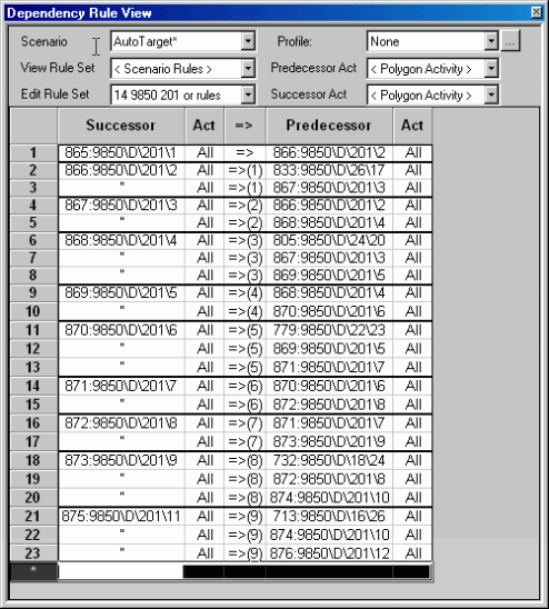
The docking Dependencies View window has a number of settings that specify which dependencies should be displayed and the rule set to which new rules will be added. This window is shown in its un-docked state below.

The Scenario drop down box is used to select the scenario that will be used when dependency rules are created. The active scenario is selected by default and it is rarely changed.
The View Rule Set drop down list box defines which dependencies will be displayed in the 3D Scene. This setting only applies when the Dependency Rule View is visible and when in use, over-rides the settings defined in the Dependencies tab of the plot's Properties window. The following options are available.
| • | None: Will not display any dependencies in the graphics image. |
| • | Selected Rules: Displays arrows to represent dependencies that will be created by the rules currently selected in the dependencies rule view. |
| • | Edit Rule Set: Displays arrows that represent the dependencies that will be created by the rule set currently being edited. This is the most common selection. |
| • | Scenario Rules: Displays arrows that represent every dependency defined in the selected scenario. |
| • | Individual Rule Sets: An entry is provided in the drop down list box for every Absolute Address rule set in the active scenario. When one of these items is chosen, arrows that represent the dependencies that will be created by the chosen rule set will be displayed. |
The Edit Rule Set drop down list box is used to specify the rule set where new rules will be added. This can be a new or an existing rule set, but it must have the type Absolute Address and must be active in the selected scenario. Alternatively the <New Rule Set> option can be selected, which will automatically create a new rule set and prompt for an appropriate name.
The Profile list box allows a release profile to be assigned to each of the dependencies created by this rule set. Any release profile can be selected or a new release profile can be created. However the same release profile will apply to all rules within the set.
The two Activity drop down boxes are used to specify the default predecessor and successor activities that will be assigned to any new rules added graphically. By default, these are set to All, but they can both be changed. The activities assigned to each rule can also be changed after the rule has been created.
The rule table in the Dependency Rule View is similar to the one used for Absolute Address rule sets in the schedule set up window. This shows any rules that already exist in the edited rule set and any new rules that are added to it.
To create a new rule, the user must first select the successor record by clicking on it. The colour of the selected block will change to blue, to emphasise the selected successor block.
To help identify blocks in the image, the record name is displayed in a tool tip for 15 seconds when the mouse is held over a block for a few seconds. The name is also shown in the status bar and this remains as long as the cursor is over the record. Additional information from any combination of fields can be also displayed with the record names by selecting a transposed field selection template in the Fields drop down box on the tool bar.
Once the successor has been chosen, its predecessors are selected by clicking on them with the Ctrl key pressed. Each of the selected predecessor blocks will change colour to red to emphasise them. The cursor will also change to an arrow with the word AND when the Ctrl key is pressed, indicating that standard dependency rules are being defined.
Once all the predecessors have been selected, the rules can be added to the rule set by selecting the successor block (the block coloured blue) for a second time, still with the Ctrl key pressed. This places a rule in the rule table for every selected predecessor, all with the same successor.
There is no need to drag blocks from the plot to the dependency rule table, as is required when creating dependencies from the schedule set up tree. Simply selecting the successor record a second time will automatically transfer the dependency rules to the table. This approach is much faster when creating dependencies graphically.
OR rule groups can also be created graphically, following a very similar process. The successor must again be selected first, but the Shift key must be pressed when the predecessors are selected. The cursor will change to an arrow with the word OR and when selected, the predecessor blocks will change colour to pink to help emphasise them.
When the successor record is selected for a second time (with the Shift key pressed), a single OR rule group will be added to the rule set containing all the selected alternative predecessors.
The type of rule set created (standard rules or an OR rule group) depends on whether the Ctrl or Shift key is being pressed when the successor is selected for the second time. Even if the Ctrl key was being pressed when the successors were selected, an alternative rule group will be created if the Shift is being pressed when the successor is selected for the second time. It doesn't really matter which key is pressed when the predecessors are chosen, providing the correct key is pressed when the successor is clicked a second time and the rules are added to the list.